


 中文
中文 Italian
 Türkçe
 Português
 Español
 Deutsch
 العربية
 Tiếng Việt
 Français
 Русский
 한국어
한국어Ms.Lizzy
Hi, this is Lizzy from Dinosaw ( Not a Robot ). Which Machine ( model ) do you want? Please WhatsApp us now
Open Hours:8:30am-20:30pm
WhatsApp: +86 198-5901-3937
 Oct 7, 20255 MIN READ
 Oct 7, 20255 MIN READ
Explore the architecture of a 5-axis waterjet, from the UHP pump (~550 MPa) to the AB-axis head, nozzle specs, and control system for precision cutting.
Understanding the core architecture of a CNC waterjet is key to leveraging its full potential. The machine’s ability to deliver bevels and complex contours in brittle materials without heat-affected zones (HAZ) stems from a precise integration of an ultrahigh-pressure (UHP) system, a sophisticated cutting head, and a rigid gantry structure.
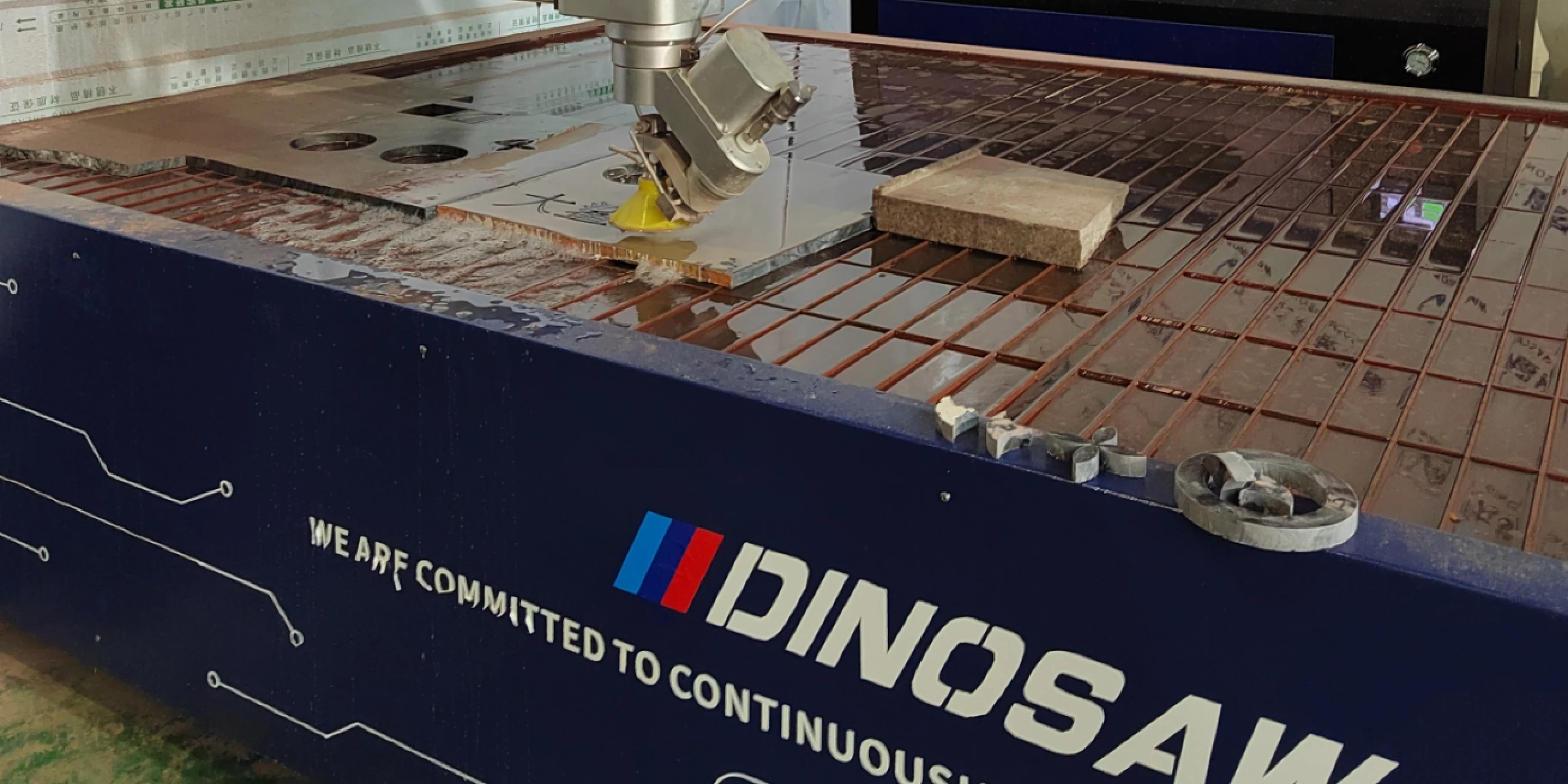
The DINOSAW 5-Axis CNC Waterjet Cutter integrates a gantry cutting table (with models like 3020 and 4020), a UHP pump, a 5-axis AB-axis head, an automatic sand feeder, and a CNC control cabinet, offering a complete system for precision manufacturing.
Get a parameter starter sheet for your materials.

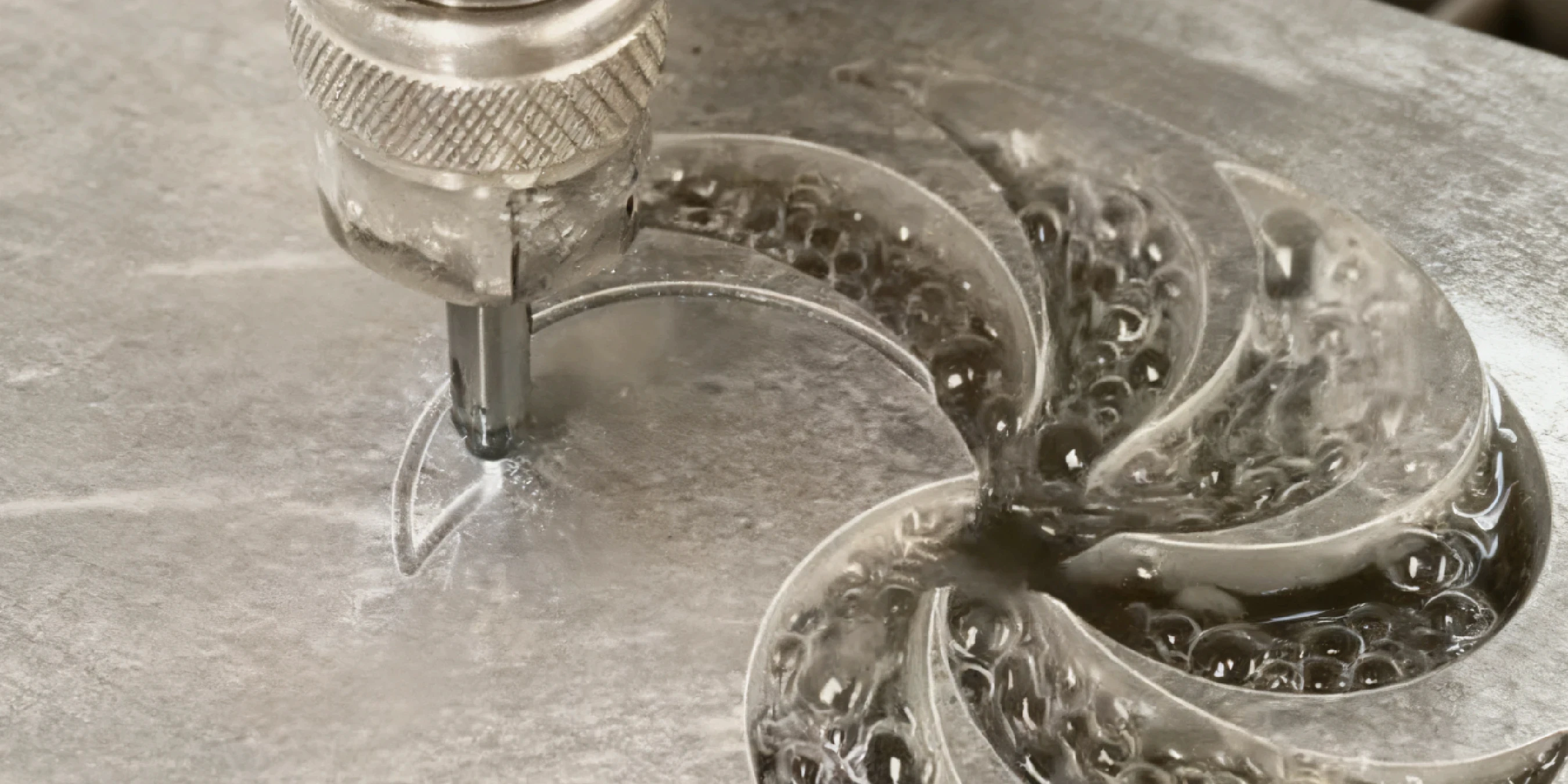
The fundamental principle of abrasive waterjet cutting is material erosion. The process starts at the UHP pump, which pressurizes water to extreme levels. This water is then forced through a tiny orifice (the nozzle) to create a supersonic stream. For cutting hard materials, an abrasive garnet is drawn into this stream in a mixing tube, and the resulting slurry exits the cutting head to precisely erode the workpiece.
The nozzle, typically made of ruby or diamond, is a critical component that focuses the water jet. DINOSAW-reported diameter ranges from 0.05 mm to 0.33 mm, with smaller orifices used for finer details. After the nozzle, the water passes through a mixing chamber where it creates a vacuum that pulls abrasive from the feed line. The water and abrasive combine in the mixing tube (sand tube), which has a typical inner diameter of 1.02 mm, before striking the material.
While a 3-axis machine operates on the X, Y, and Z planes for 2D profiling, a 5-axis machine features an articulating AB-axis/AC-axis head. This allows the cutting head to tilt and rotate, enabling the machine to cut complex 3D shapes, beveled edges, and compensate for taper, which naturally occurs in thick materials. This is essential for applications like weld preparations and creating seamless mitered edges on countertops.
Motion is controlled by high-precision servo motors. The gantry system allows for rapid positioning, with X and Y axis running speeds up to 6000 mm/min . The Z-axis travel of approximately 90 mm provides ample clearance for various material thicknesses and fixtures, and includes an infrared altimetry function for maintaining a consistent standoff distance from the material surface.
The heart of the system is the UHP intensifier pump, which can achieve a rated pressure of 550 MPa , though typical working pressures range from 350–390 MPa. This pressure is generated by a hydraulic system driving a plunger assembly. During operation, oil temperature can rise, affecting seal life and performance. A cooling tower is integrated to maintain stable oil temperatures, prolonging the life of high-pressure components and ensuring consistent pressure delivery.
The entire system is managed by a CNC controller with an intuitive Human-Machine Interface (HMI), available in Chinese and English. The software automates complex calculations, such as cutting time, and controls parameters like pierce delays and feed rates. For safety and process control, the system includes multiple interlocks and is designed for compatibility with standard factory automation hardware like PLCs and drives.
These are wear items inside the pump.
The abrasive stream erodes these components over time.
Moisture or inconsistent abrasive can cause blockages.
A smaller nozzle orifice (e.g., 0.25mm) paired with a corresponding mixing tube is often preferred for fine details and better edge quality on brittle materials like sintered stone.
Seals are critical for maintaining pressure in the UHP pump. As they wear, water can bypass the seal, causing a pressure drop and reducing cutting efficiency.
The machine's control cabinet provides I/O points that can be wired to a central PLC to monitor states like emergency stops, pump status, or cover open/closed, ensuring safe integration.
An AB-axis/AC-axis head is essential for creating beveled edges, performing taper compensation on thick parts, and cutting complex 3D shapes. For simple 2D cutting, a 3-axis head is sufficient.
For shops running the machine for multiple shifts in a warm climate, upgrading the cooling tower or ensuring it is properly sized is recommended to maintain optimal hydraulic oil temperature and protect the pump.
 English
Get A Easy Solution
Chat Online
Hi, this is Lizzy from Dinosaw ( Not a Robot ). Which Machine ( model ) do you want? Please WhatsApp us now
Hello 👋 How can we help?